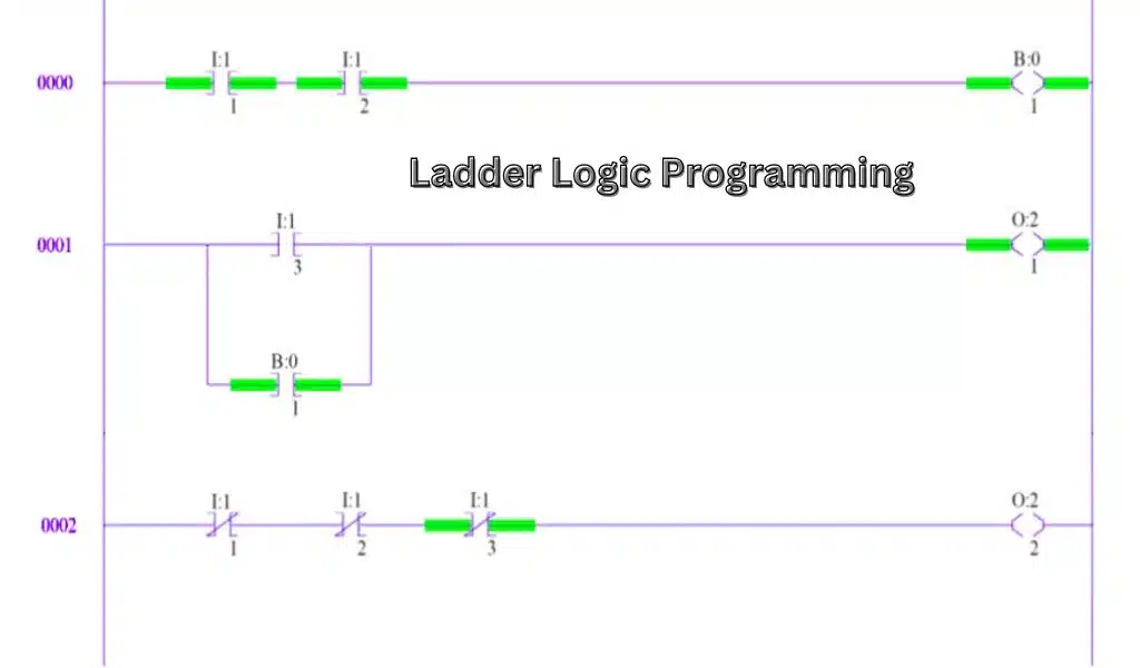
Ladder logic programming is a programming language based on circuit diagrams. Programmable logic controllers (PLCs), which are employed in industrial applications, are the main target audience.
Since each relay rack is represented by a symbol on the ladder diagram with connections to devices below it that resemble vertical rails, the language has grown from being a way to describe the design and construction of relay racks used in manufacturing and process management. The relay symbols themselves resemble ladder rungs.
Application Scenarios of Ladder Logic Programming
On the ladder logic programming, each system in the relay rack will have a symbol indicating the relationships between the various devices. The schematic of the ladder will also include additional items beyond the relay rack, such as pumps, heaters, and so on.
- The relay logic hardware circuit diagrams have evolved into the ladder logic programming language, which describes a system through a graphical representation.
- Industrial control applications employ ladder logic, which is used to create software for programmable logic controllers (PLCs).
- Ladder logic is helpful for redesigning outdated hardwired relay circuits as well as for simple yet crucial control systems.
- Due to the advancement of programmable logic controllers, this has also been utilized in highly sophisticated automation systems. Instead of being a language of procedures, ladder logic should be thought of as a language of rules. A rule is represented as a ladder “rung.”
Strengths of Using Ladder Logic Programming
Self-Documenting and Intuitive: An effective graphical depiction of circuit design principles is provided by a ladder diagram. The learning curve to begin using a ladder diagram is quite low due to the familiarity of the environment; fundamental programming skills emerge fast. Due to this, the ladder diagram is particularly well-liked for applications that require employees without software skills to debug or maintain them, such as some electricians or plant technicians.
Outstanding Debugging Tools: A ladder diagram with contemporary internet debugging tools provides an animation of a live “power flow.” This makes it very simple to comprehend the logic of the diagram and to track any errors.
Discrete Logic Representation That Is Effective: A ladder logic program makes sense to illustrate discrete logic because it is made to resemble electrical circuits. A ladder diagram is almost intuitive for digital logic.
Benefits of Using Ladder Logic Programming Language
A ladder logic programming offers an excellent schematic interpretation that is concentrated on well-known circuit architecture principles. Due to the environment‘s accessibility and the low learning curve required to get started with a ladder diagram, basic programming skills develop quickly. The ladder logic programming has been particularly popular in applications involving personnel without technical expertise to manage or repair, such as specific electricians or plant specialists. Since the programming language is designed to represent electrical circuits, it is ideal for expressing abstract logic. For digital logic, the language is rather simple to understand.
Get the Best Result with Ladder Logic Programming
When it is necessary to control production operations and processes sequentially, ladder logic is frequently utilized in industrial settings to program PLCs. The programming language is very helpful for creating new programmable versions of older hard-wired systems or for creating basic yet crucial systems. A lot of this programming language is also utilized in extremely complex automation systems, including those in electronics and auto manufacturers.
The premise behind ladder logic is that because it uses common and well-known technical symbols for programming, even employees without programming backgrounds can program quickly. However, this benefit is quickly lost because PLC manufacturers frequently bundle ladder logic programming systems with their products. These systems frequently do not use the same symbols and conventions as those created for PLC models from other manufacturers; in fact, the programming system is typically intended only for specific models, making it difficult to port existing programs to other PLC models or necessitating a complete rewrite.