
There aren’t many components that have such a fundamental role to play in electronic circuits as capacitors do. A capacitor has its name because of its “capacity” to store energy – indeed, it has been likened to a tiny, rapidly charging and discharging battery.
The term “capacitance” refers to the ability of an object or device to store electrical charge. This ability is measured in farads (F), although in practical “real-world” contexts, such units as microfarads (µF) and picofarads (pF) are more commonly used.
But of course, a capacitor isn’t a battery; it is far simpler, having the ability to store electrons, but not to produce new ones.
The Essentials of What a Capacitor Is
A capacitor is made up of two conductive plates, separated by an insulating material known as a dielectric. The application of a voltage causes positive and negative charges to build up on the two plates, thereby storing energy.
Though capacitors evolved but their main task is to store an electrical charge and release it when required. This makes them useful for applications needing a high-voltage burst, such as camera flashes. These components are also helpful for such purposes as power supply smoothing and signal filtering.
Such benefits mean capacitors find their way into all manner of electronic systems and projects, ranging from power supplies and radios to smartphones and electric vehicles (EVs).
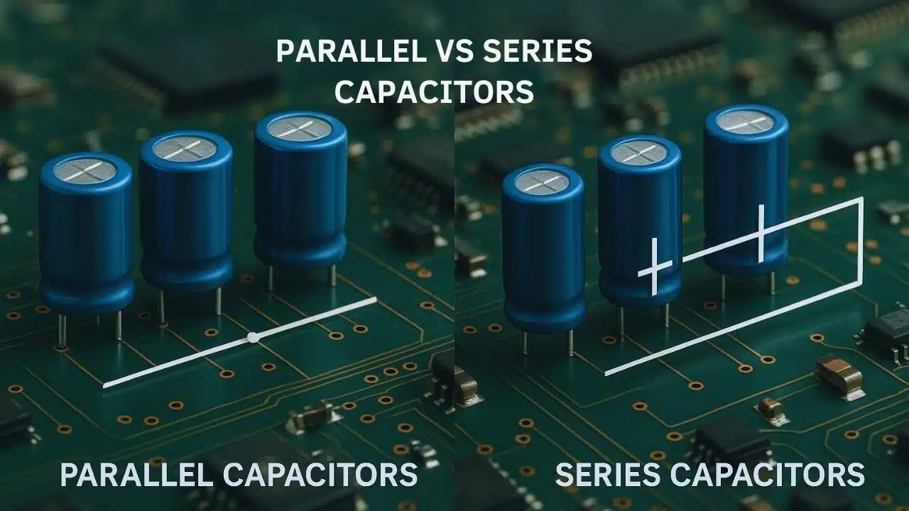
An Introduction to Series and Parallel Capacitors
When capacitors are connected in a circuit, they may be arranged in parallel, or in series. It matters to know the differences between these two configurations, because all this has a major impact on the total capacitance, voltage handling, and overall behaviour of the circuit.
Parallel Capacitors: Adding Up Capacity
A parallel configuration involves capacitors being connected side by side, with their positive terminals joined and negative terminals joined. This arrangement enables current to flow through each capacitor independently – in effect, combining their storage capacities.
So, the total capacitance in a parallel circuit is simply the sum of the individual capacitances. This can be expressed as: Ctotal = C1 + C2 + C3 + …
In the event, then, of a 10 µF capacitor and a 20 µF capacitor being connected in parallel, the total capacitance would be: Ctotal = 10 µF + 20 µF = 30 µF.
When capacitors are connected in a parallel arrangement, the voltage across each capacitor stays the same, equal to the supply voltage. However, the total charge stored is the sum of the charges on each capacitor.
Series Capacitors: Dividing The Load
If, on the other hand, a series configuration is used, this entails the capacitors being connected end-to-end in a single path. While the charge stored on each capacitor is the same, the voltage divides across them.
To calculate the total capacitance in a series circuit, this reciprocal formula can be used: 1/Ctotal = 1/C1 + 1/C2 + 1/C3 + … If only two capacitors are connected in series, this can be simplified to Ctotal = (C1 x C2) / (C1 + C2).
Let’s apply the example, then, of a 10 µF capacitor and a 20 µF capacitor being connected in series. The calculation for figuring out the total capacitance here would be: Ctotal = (10 x 20) / (10 + 20) = 200 / 30 ≈ 6.67 µF.
In a series arrangement, the total capacitance is always less than the smallest individual capacitor. As for the voltage across each capacitor, this will depend on its capacitance, with larger capacitors taking a smaller share of the total voltage.
Conclusion: It Is Critically Important to Be Aware of These Distinctions
If you are reading this as someone designing or troubleshooting electronic circuits, you will need to know about both series and parallel capacitors, and the differences as laid out above.
Possessing this knowledge and understanding will put you in a strong position to choose the right configuration for every circuit project you take on. In the process, you will be better placed to optimise performance, enhance safety, and fulfil the design goals for your circuit.